Comments? email to
![]()

![]()
| Here's
a practical amplifier for portable use. This one uses a pair of Mitsubishi
MosFet amplifier modules. The outputs from the two amplifier modules are combined using branchline hybrid couplers made from PC board material. I used Teflon for the output coupler to keep the losses low, and to better handle the higher power levels. The amplifier also utilizes a sequencer and a low-loss antenna transfer switch. Power requirements are 13.5v @ 18a (at full output of 65w). |
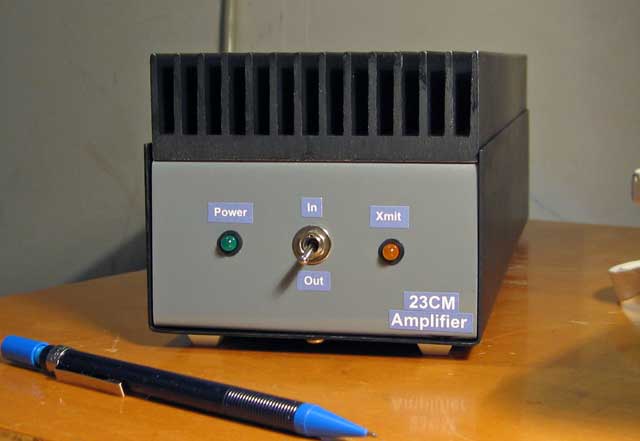 |
| I kept the rear panel simple, yet versatile enough to allow
for expansion. Like most of the solid-state 'bricks', all one needs to do is connect power, a PTT line from the radio, an antenna and the transceiver or transverter. If one wished to use this as a driver for a larger amp, the transfer switch can be bypassed, and the internal amplifier accessed directly via the bulkhead SMA connectors on the left. These are normally jumpered to the transfer switch as shown. |
 |
| Here's
a view of the inside, showing the transfer switch on the right and the R.F.
components in the middle. On the left, mounted on a vertical bracket, are the sequencer and 28v boost boards (this boost board supplies 28v to the transfer switch). |
 |
| The R.F. portion begins with an input coupler, then two 30w amplifier assemblies followed by the low-loss output coupler. |
 |
| This
little board is the input attenuator, consisting of a 12 db
directional coupler, and an additional 3 db chip resistor pad. The amplifier was to be used with a 10w radio, and without the input attenuator, would only require 250mw for full output. Even with this attenuator in place, only 6w drive is really needed. |
 |
| Another builder (Steve Miller, W6QIW) built a similar
amplifier to replace his 30w mast-mounted amp/preamp. This one also has a preamp integral to the box, and because it is used with about 200mw of drive, does not use an input attenuator. The amplifier is essentially the same, though I must admit I like his construction techniques more than my own. With 13.5v @ 19a, he is getting 75-80w out. |
 |
| Additional information, including development data on the various components, can be seen by clicking on the current projects link listed in the navigation bar on the left (near the top of this page). The sequencer and 12 to 28v booster boards are also described in detail via the navigation links. A block diagram of the complete amp is shown in the picture below. | |
