Comments? email to
![]()


This first section deals with inexpensive general purpose relays you can use for low to medium power through 220MHz, up to about 200w.
The second section (below the first), deals with inexpensive
general purpose relays you can use from HF through 2m at full legal limit
(1500w+). Click here if you'd like to skip directly to the
second section.
 And
for those of us needing an inexpensive relay for the uhf and lower microwave
bands, the HF3 series of tiny relays made by Axicom will handle up to 50 watts
with switching times as low as 3 milliseconds; these are not general purpose
relays, and are designed for RF switching. The relays themselves can be
purchased with coil voltages ranging from 3v to 24v; the one in this photo is a
12v unit, shown next
to a dime for perspective. Click here to skip to the
section detailing this one.
And
for those of us needing an inexpensive relay for the uhf and lower microwave
bands, the HF3 series of tiny relays made by Axicom will handle up to 50 watts
with switching times as low as 3 milliseconds; these are not general purpose
relays, and are designed for RF switching. The relays themselves can be
purchased with coil voltages ranging from 3v to 24v; the one in this photo is a
12v unit, shown next
to a dime for perspective. Click here to skip to the
section detailing this one.
Sometimes you can use inexpensive components as a replacement for the more exotic ones. I needed an input relay for one of my VHF amplifiers (up to 200w or so), and had a few inexpensive Omron G2 series laying around, so let the testing begin.
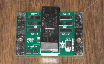
These are pretty good little relays, and can be purchased in 8A (DPDT) or 16A (SPDT) configurations with many coil voltage options. The photo here shows one of them mounted on a small PC board to facilitate connections; the board itself is quite small, only about 1.5 by 2 inches. When mounting, the back side of the board should be elevated above conductive surfaces with 3/16 (or longer) spacers.
There are provisions on the board for reactance compensating components (C1 and C2), but in most cases these can be jumpered over at 2m and below. They become useful above 150MHz on the DPDT relay (more on this later).
The testing I did was on the 12v types, both DPDT and SPDT, and here are the results:
SPDT type G2RL-1
C1 or C2 not used, and the C2 gap on the board jumpered. Since this is a SPDT type, only the C2 side was used, which presented the best load match. The extra unused pins on the relay were cut off flush with the component body, and the relay was elevated above the board about 1mm for clearance.

The insertion loss is outstanding, from DC up to about 500 MHz, a nice surprise.

Here's the return loss, showing SWR less than 1.1 to 1 past
500 MHz.

And the only disappointment was the isolation, fairly low at
VHF, and even lower at UHF. Not a problem for an input relay, though, unless you
are switching past a preamp.
DPDT type G2RL-2

This relay also had very low insertion loss all the way past 1 GHz.
A 150pf capacitor was used at C1 for this
measurement, which degraded the insertion loss below 50 MHz, so for 6m and
below, no compensation is needed. The compensating capacitor did improve return
loss at 2m and above, which is shown in the next two plots.

This is the return loss without compensating capacitors ar C1 or C2.
Below 2m, compensation is not needed; it's still
acceptable up to 1GHz, but improves with compensation (next plot)

With a 150pf capacitor at C1 (or C2) the return
loss improves quite a bit below 800 MHz, but you can see where this actually
impairs performance below 100 MHz.

Isolation is better than the SPDT relay, but
still fairly low above 150MHz.
A High Power Alternative Using General Purpose Relays
 If
you can afford them, the relays shown to the right are the most commonly used
from HF through microwave. The Dow Key units are very expensive (hundreds of $)
unless you can find them surplus, but are also pretty much the gold standard,
useful to 12.4GHz.
If
you can afford them, the relays shown to the right are the most commonly used
from HF through microwave. The Dow Key units are very expensive (hundreds of $)
unless you can find them surplus, but are also pretty much the gold standard,
useful to 12.4GHz.
The Tohtsu relay (with the blue coil) is of
moderate cost ($120 or so as of this writing, and useful up through 1.3GHz.

Here's a small collection of general purpose relays; they are not coaxial, and they were not designed to be used to switch RF power, but they will. None cost more than about $5. I tested quite few of these, and found that one in particular was quite useful through 6 meters without having to do anything but make a small PC board to facilitate connections. With a few small components to compensate for stray reactance, you can even use it at 2 meters at full legal power (1500w).
The one I'm referring to is the smaller one to
the right of the board and above the coin; above it is one with it's case cut
away to show the internal construction. Contact bars are very short, the
contacts themselves are rated at 16 amps, and they are nowhere near any metal
support structures; the entire support mechanism, and the actuator that moves
the center contact is plastic, providing good insulation through VHF.

Since this relay is not coaxial, it has a bit of stray capacitance between the contacts, and some inductive reactance; this limits it's useful frequency range.
The capacitance affects mostly isolation, and the inductance affects SWR (return loss), though both affect each parameter to some extent. Without any compensating components (just the relay mounted to a PC board), the useful frequency range is roughly DC through 6 Meters.
The schematics to the right show the capacitive
influence to the normally closed (NC) and normally open (NO) positions.

Insertion loss, with or without compensating components, is next to nothing (less than a tenth of a db), so we'll ignore that measurement in the following discussion.
Looking at return loss (SWR) first, the red line shows the uncompensated data, and it's OK up to about 80MHz or so, then degrades to about 1.3 to 1 at 2 meters.
By just adding 5pf across the port in use (NO or NC), that port's return loss improves dramatically far above 2 meters (green plot).
Some additional experimentation also improved
response at 222 MHz (1.2pf shunting all three ports), but there were other
issues concerning high power above 2m, so we'll stick to that band as the upper
limit for now.

Looking at isolation now, we're OK up through 6m, but at 2m it's getting to be a problem. Even at 6m, it's roughly 30db.
If you will be using this relay as part of the antenna switch in an amplifier, a good rule of thumb is to have at least 15db more isolation than you have amplifier gain. At 6m, LDMOS amplifiers can have 30db gain, so that extra 15db margin will need to be made up by the input relay. That said, most have at least that much isolation, even the inexpensive ones described above.
To be able to use this at 2m, it would be best to
improve the isolation some...even if the difference is made up by the input
relay, having up to 10w sitting on the open contacts can be tolerated, but isn't
that comforting.

Here's what the complete circuit looks like when compensation for both SWR and isolation is added to the board.
When I first though of using the stray capacitance of the relay itself as part of a parallel trap (like we might use on HF antennas), I wasn't sure it could be that easy ...but I was very surprised it actually worked as well as it did.
For 2m, adding an inductor across the NO and
NC contacts did the job, as the analyzer display (below) shows.

Doing this really isn't necessary if your input relay is mounted close to the output relay, and that input relay has adequate isolation to get that 15db margin I spoke of before.
But you can see how effective this is in improving isolation; it went from about 23db to more than 40db over the entire 2m band.
One thing else you'll notice here...this inductor
degrades low frequency isolation. As the 'trap' becomes non-resonant below 2
meters (red plot), isolation gets worse and worse. For this reason, if you
decide to use the inductor, use it only for 2m.

For those of you wanting to use this relay as your output switch, the board shown here is available on the parts page. It should be mounted above any conductive surface using 3/16 or 1/4" spacers.
I had the board made from .094 FR4, 2oz copper (ok through 2m up to 1.5kw). It has grounded pads next to each port to accommodate compensating chip capacitors if you should need to use them (2m).
The Cornell p/n for the 5pf 1kv mica chip caps is
MC12CF050D-F, and these are available from
www.mouser.com and other suppliers.
 These
HF3 series relays are good to 3 GHz, but using inexpensive FR4 for the PCB
limited their best performance to about 1.75 GHz. They were designed for surface
mounting, so one does need to have a suitable PCB made to be able to use them
properly.
These
HF3 series relays are good to 3 GHz, but using inexpensive FR4 for the PCB
limited their best performance to about 1.75 GHz. They were designed for surface
mounting, so one does need to have a suitable PCB made to be able to use them
properly.
It took me a couple of tries to get the size of the traces correct so the assembly would work well through 1296, and it does do that; let's look at some of the data (below).
Here's typical return loss measured using this PCB

Next is the measured insertion loss

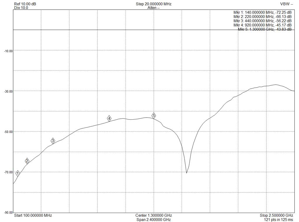
And finally, isolation; even at 1300 MHz it's greater than 40db...and much higher below that frequency. Because the isolation is good, one practical application for this one could be protecting an LNA on the receive port of a septum feed horn for EME on 1296; and of course, it would also make a good relay for the input of an SSPA (up to 50w).