Comments? email to
![]()
A 1.8 to 54MHz High Power Combiner Set

 For
those who want to be able to combine amplifiers to get to the legal limit, the
coupler set shown here will get you there easily. When used with two of the
1kw RF decks (1.8
to 54 MHz), the result is an amplifier that will just loaf along at 1500w
with lots of headroom.
For
those who want to be able to combine amplifiers to get to the legal limit, the
coupler set shown here will get you there easily. When used with two of the
1kw RF decks (1.8
to 54 MHz), the result is an amplifier that will just loaf along at 1500w
with lots of headroom.
The top one, shown with it's 100 ohm 500w isolation resistor (positioned in the cutout slot) will combine the outputs, and the smaller unit at the bottom deals with the inputs.
These are "in phase" couplers, meaning the inputs are combined in phase with one another. Each consists of a 2 to 1 coaxial hybrid combiner (or splitter) and a 2 to 1 transformer to return the combined (or split) impedance back to 50 ohms.
These measure only 2.5" by 4.5" and 1.625" by 3.625" respectively, and except
for the high power isolation resistor on the output coupler, do not require heat
sinking, as the insertion losses are very low. .094 FR4 is used for the high
power board substrate, and the more common .062 FR4 for the lower power board.
 Here's
a close-up showing how the output coupler's isolation resistor is mounted and connected. On the
input coupler, a pair of 3w metal film resistors is used (power requirements
there are small), but larger resistors can be used there if higher power levels
(>25w) need to be handled.
Here's
a close-up showing how the output coupler's isolation resistor is mounted and connected. On the
input coupler, a pair of 3w metal film resistors is used (power requirements
there are small), but larger resistors can be used there if higher power levels
(>25w) need to be handled.
When I was trying to figure out how to do this, I got dizzy reading about all the various (and complex) methods, so for my own sanity, I decided to keep things as uncomplicated as possible. I need to give credit to Motorola application note AN749, where on page 5, figure 7B, there is a description of a basic hybrid coupler. The only drawback was the 2 to 1 impedance transformation, leaving one with a 25 ohm port to match back to 50 ohms somehow.
But it turned out to be relatively easy to figure that one out; most broadband transformers convert impedances by the square of the turns ratio; for example, a 2 to 1 turns ratio will yield a 4 to 1 impedance transformation; a 3 turns to 1 yields a 9 to 1 ratio, and so on.
OK, so for a 2 to 1 transformation, we need a turns ratio that is the square root of 2 (or 1.4142). Well, it turns out that a 5 to 7 turns ratio will yield a 1.4 transformation (close enough).
 I
chose 5 to 7 because it gave me the ratio I needed with the fewest number of
turns; too many turns, and bandwidth gets limited...and we needed to get 160m
and 6m in there. An autotransformer was the choice for this, and this schematic
shows the basic method. I used coax for the first 2 turns because of the tight
coupling and lower losses.
I
chose 5 to 7 because it gave me the ratio I needed with the fewest number of
turns; too many turns, and bandwidth gets limited...and we needed to get 160m
and 6m in there. An autotransformer was the choice for this, and this schematic
shows the basic method. I used coax for the first 2 turns because of the tight
coupling and lower losses.
Here's the complete schematic for the coupler. A small amount of capacitance (C1) is used to compensate for stray reactance, and is most effective at the top end (6m).
R1 provides the isolation between port 1 and port 2, and must have a power
rating at least ¼ the total power at the common port. C1 should be a high
current mica type, 22pf and a 1kv rating for up to 2kw as an output combiner,
30pf and a 300v rating for up to 200w as an input divider. A small SMT 1206 size
ceramic chip capacitor can be used in place of the 30pf mica if driving a pair
of the HF KW amps described here, as
the most input power required in this case is less than 5w.
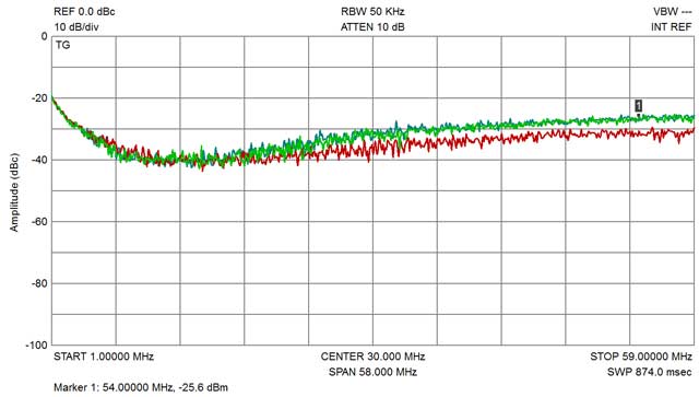
Performance measurements are shown below:

There isn't much lost in the output coupler, only about a tenth of a db at
the high end, and the coupling tracks closely.

And here's the input coupler; this one loses about 2 tenths due to the
smaller cores used in it's transformers, but it's still next to nothing, and on the input side this is hardly a
concern (we usually have to throw away some drive power anyway).

Back to the output coupler, here's the isolation; should one of the combined
amps ever fail, the remaining one is well protected.

Plenty of isolation on the input coupler also...
And here's the output coupler return loss on all 3 ports, less than 1.1 to 1
VSWR from 1.8 to 54 MHz. SSPA's do like a good match, and we have it here.

And the same goes for the input coupler...
One final note...after using the couplers for some time, I noticed the T2 core
on the output transformer ran hot on 75m, and very hot on 160m. The solution was
to "double up" to a binocular core for T2 (only on the output coupler) as shown
below.
