Comments? email to
![]()

For the IC9700 or any other radio capable of controlling an external LNA directly, skip to that subsection here
A mast-mounted LNA can be very helpful, especially for EME, and in many cases for terrestrial weak-signal work on the higher UHF and microwave bands. One problem nagging most users of these sensitive little amplifiers is how to protect it from the station transmitter, and this problem is particularly severe above 100 milliwatts.
Some of the commercial self-switching LNA's available today are able to handle as much as 100 watts, and that's pretty much the upper limit. These units are expensive, mostly due to the internal circuitry that must be incorporated into the LNA enclosure. And what about power levels above 100 watts? What I'm going to describe next are my own techniques for solving the problem; they are certainly not the only ones, just the ones I have experience with and used successfully.
I did an initial write-up and prototyping on this subject a few years ago, and this material can be viewed here. If you've read this, you are probably aware that the absolute safest way to protect the LNA is to use split transmitter and receiver connections with a separate transmission line for the LNA-to-receiver connection. If this is not something you can or want to do, your solution will be less bullet-proof, but you can still have a fairly reliable setup. For the descriptions below, I'm going to assume a failsafe high-power relay resides with the LNA at the antenna, the LNA is bypassed by this relay by default (un-powered state), and that the power to operate the relay and LNA is applied using a separate connection. Some systems use the main transmission line with bias tees to also carry the DC power to the LNA, but to make things easier to describe, I'll assume a separate power wire.
When I finished developing the Amplifier Control Board (also featured in the link bar on the left), it occurred to me that even though this board was designed as a control board for high-power amplifiers, it was also a good solution as an LNA controller. More on this in a moment...
![]() For
those of us using a transverter, adequate protection can be as easy as a
sequencer. A typical setup is shown to the
right.
For
those of us using a transverter, adequate protection can be as easy as a
sequencer. A typical setup is shown to the
right.
In this example, no RF is going to get up the transmission line unless the sequencer keys the transverter, which it will not do until it has the LNA powered down and safely bypassed.
Event 1 turns off the power to the LNA, placing it into it's default state (bypass mode).
Event 2 keys the transverter, making it free to generate RF.
Note that although the transceiver is generating RF before the LNA is bypassed, no RF goes up the transmission line until the transverter is active and makes the conversions.
An amplifier can follow the transverter, and can also be keyed
by event 2 or any other sequencer event after event 1.
OK, now let's describe another typical setup, where you have a
transceiver only (no transverter) and possibly an amplifier. Without some special controls,
as soon as you key radio PTT, RF is on the transmission line and the LNA is
damaged before it can get itself out of the way, even if you are using a
sequencer. The problem is the radio...as soon as PTT is engaged, you have RF
output, and the fastest relays in the world can't stay ahead of it (they need at
least 20 milliseconds to switch over). Now we need to hold off RF from the radio
while we get the LNA out of the way.
Every transceiver worthy of using has an ALC input, and this can be used to control RF output during this critical switching time. The Rev 6 amplifier control board has the necessary functions to do this. Here's how it works:
When the LNA is switched on, the control board also powers up. It immediately generates a negative ALC voltage, which is fed to the radio to prevent it from releasing RF. When the radio is first keyed, no RF is sent up the transmission line because of this ALC voltage.
At the same time (key-up), the first thing the control board does is bypass the LNA (event 1 of it's internal sequencer). In this example, it does this by shutting down the FET switch feeding power to the LNA.
At event 2, you can key up an amplifier
At event 3, the ALC is released and RF is allowed to be generated by the transceiver.
When the LNA is manually switched off, so is the control board, and the radio operates normally (there is no ALC blocking signal generated).
There are two obvious risks with this system, and the first is losing the ALC connection to the radio; if this connection is not present, or becomes unplugged, the LNA can be damaged.
The other risk is driver instability. Some radios emit a short
burst of RF at key-up, whether or not the ALC is blocked. This is usually caused
by an oscillation in the final stage of the radio, so it's always wise to test
your system before going live with the LNA.
The IC9700 and external LNA's
If you own an IC9700, you have a radio capable of controlling a mast-mounted LNA all by itself with just the help of a bias T. And on 70cm and 1296 in particular, the 9700 does need some help in the receive department.
The radio is capable of powering an LNA by sending 12v down the center conductor of the coax on any of the 3 bands (144, 432, 1296). However, this method does have some limitations:
- using this method, the 9700 has a current limitation of 200 ma. for the 12v it can supply down the coax, and this is usually not enough to power a couple of 12v relays and an LNA at the same time.
- sending 12v down the coax is clever, but there are long-term problems some have experienced with noise caused by 12v leakage from moisture penetration in the feed lines, and this is usually caused by long-term exposure to the elements.
- many affordable surplus relays are 28v types, and cannot be operated from a limited 12v power source.
With the help of an uncomplicated bias T located near the radio, these limitations can be overcome.
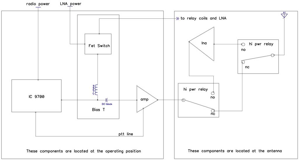
This first diagram shows a typical setup for long feed lines where a mast-mounted LNA would help; this is particularly useful on bands where external noise is not a limitation, as when the use is for EME where the antenna is not on the noisy horizon. It can also be just as useful for terrestrial work where external noise may also be low enough to make an LNA useful.
The advantage of this system is that it requires only a single feed line with the LNA located right at the antenna feed where it will do the most good. The big disadvantage is the requirement for (expensive) high power relays with enough isolation to protect the LNA when in it's default (unpowered) state.
The 9700 controls both the switching and sequencing of the LNA. In the radio's menu system, the external LNA is set to 'on' and the transmission delay set to 30ms. These are per-band settings, and this connection scheme can be used on any of the 3 bands mentioned; here are the sequence of events:
- Radio is receiving
12v is sent down the coax to the Bias T (located near the radio). The Bias T separates the 12v from the RF via the RF choke and DC blocking capacitor, and uses the 12v sent from the radio to turn on a FET switch (part of the bias T board). The FET switch takes power from an external source (12v or 28v) for whichever relay type you are using to switch the LNA in or out, and sends it to the relays and LNA using two wires. These wires can be a couple of extra conductors in your rotator cable or a separate pair.
- Radio is transmitting
The 9700 immediately turns off 12v to the bias T, causing the LNA power to be disconnected and the LNA relays to go to their default (unpowered) state. This gets the LNA safely out of the way. 30ms later, the radio begins sending RF down the coax.
When the radio goes back to receive mode, transmit RF is stopped immediately; then the 9700 activates the relays to switch the LNA back online.
This second diagram below shows a connection scheme used for EME on 1296 where the typical operating conditions for the antenna system involve using a dish antenna with a septum feed. In this case, separate feed lines are used for TX and RX at the antenna, with the LNA mounted right at the feed horn; the amplifier might be mounted at the back of the dish or close to it, and a single feed line would then be used to go back to the bias T and radio at the operating position. The same sequence of events happens as in the other example above.

The big difference in this system is the placement of not only the LNA, but also the power amplifier right at the antenna, with the following advantages:
-
There is no need for high power relays because the TX and RX antenna ports on the septum feed have more than 20db isolation between them. The lower power level from the driver is the most any of the two relays will have to handle. One can use small inexpensive low-power sma type relays so long as they have adequate isolation to protect the LNA in it's default (unpowered) state.
-
Huge transmission lines can also be eliminated if enough drive power is available for the power amplifier in use.
-
The power amplifier does not have to use any antenna changeover relays, and this also reduces the cost of the system.
There are other variations of either connection scheme shown here, but these are probably the most widely used.
Some detail on the bias T would be in order, so here is the schematic for it with values for C1, C2 and L1 shown for 1296:

The current required from the 9700 is only 15ma, well below the 200ma limitation; it is only used to activate Q1 and thus Q2, the bias switching FET. The power source for the switch should be current limited to a few amps max, as a short circuit on the output could kill the FET. Shorts are common in antenna-mounted LNA systems where the elements and rotor movements can cause troubles. Don't use a fuse though, they're not fast enough...a small power supply capable of no more than 3 amps or so would be ideal.
Here's a photo of the original prototype mounted in a small 3 x 4 box I made from some aluminum sheet:

At 1296 I could measure very little insertion loss going through the T (under 0.2db), and the return loss was > 27db.
The bias T board is available on the parts page in the "Multipurpose items" section.