Comments? email to
![]()

 Running
all the solid-state amplifiers in the station used to require several power
supplies, and finally I decided it was time for an upgrade.
Running
all the solid-state amplifiers in the station used to require several power
supplies, and finally I decided it was time for an upgrade.
This one handles everything, and has capacity to spare: 13.8v, 28v and 50v, at a total of 60 amps continuous, enough to run any legal limit SSPA. But what I like about it the most is how quiet it is, very unlike the surplus "server" supplies I was using, which tended to wear me down with all that acoustic racket.
To make this one, I used eight 350w switching power supply sub-units, which I bought online for about $45 each. I selected these in particular because they were very quiet, with their cooling fans running at speeds matching how hot they get. Most of the time, the fans don't run at all, but when they do, the slower speeds engage first, and make very little noise.

These individual units are connected in a series-parallel
arrangement, and a simplified diagram of this method is shown below:

This is just the basic idea...to get 60 amps, a bit of combining is necessary; and 60 amps is the total current that can be delivered at any one time; for example, let's imagine we draw 10 amps from the 13.8v output and 5 amps from the 28v output. This leaves a total of 45 amps more available at any of the 3 outputs.
The reason for this is because the very bottom power supply must contribute to each output; it's capacity is 60 amps, so if it is already contributing 15 amps between the 13.8 and 28v outputs, it only has 45 amps left to contribute. In my own case, this is more than enough, even if I'm running radios, transverters, and a legal limit 50v amplifier at the same time.
The following block diagram shows additional detail:

A pair of 30 amp 12v supplies provide the base output (13.8v @ 60 amps), and have their currents summed with high current schottky steering diodes to keep them from bothering one another. The diodes also do a good job of providing current sharing, and the returns of the two units are tied together and routed to chassis ground through a current metering shunt, where the total current from all outputs is measured.
For 28v, the return side of a second pair of 12v supplies (set to 14.2v) is connected in series with the first pair, before the steering diodes. Connecting in this way limits the IR losses from the diodes, which can drop as much as 1/2 volt under full load. This way, there is always only one set of diodes in line with any output. As with the first pair of outputs, the outputs of the second set of supplies is combined through high current diodes.
For 50v, two sets of 24v 17 amp supplies (set to 22v) provide the last output, connected as shown.
There is an inrush current limiting resistor on the 240v
source input to all supplies; this resistor limits the turn-on surge current so
the AC on/off switch won't weld shut, as inrush currents will far exceed the
ratings of the switch. In just a fraction of a second, this resistor is bypassed
by a set of relay contacts as the supplies come up to voltage and the inrush
current subsides.

Even though the PSU sub-units have individual
temperature-controlled cooling fans, the warm exhaust air will need some place
to go once all of these are inside a cabinet. So on the back panel there are two
60mm 15cfm fans (quiet ones) that are also temperature-controlled. When the
inside cabinet gets to 115f, they come on, one mounted on the bottom of the rear
panel bringing in cool outside air, and one at the top of the panel pushing warm
air out. When the inside cabinet temperature falls to 95f, they shut off.
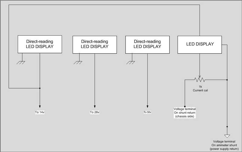
Metering is provided by four snap-in LED displays. The voltage displays are direct-reading, requiring no dividers.
The current meter is different in that it is a 75mv full-scale
display. So on this one, a trimmer resistor is provided for calibration.

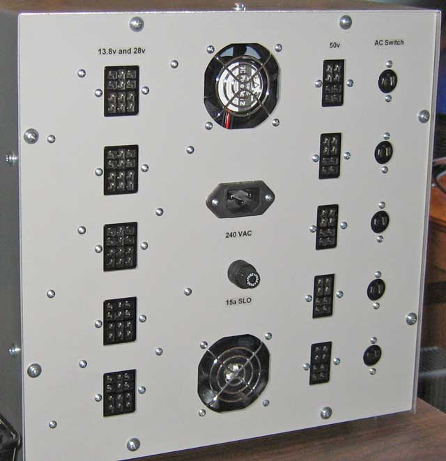
This next photo shows how the sub-assemblies were mounted inside the cabinet (cabinet dimensions are 12 x 12 x 12 inches). This is the front panel side.
Steering diodes are mounted on the 3mm thick floor plate for heat sinking.
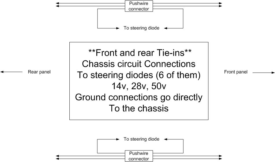
There are 3 Molex interconnects provided for the removable front panel.
The small black and clear wire connectors joining all the
paralleled wiring are push-wire connectors, requiring no soldering, and good to
20 amps each. As wired, they will need to carry a max of only 15 amps.

The rear panel side of the stack is also set up with Molex interconnects.
Mounted on the floor plate are the fan control circuit board
and the inrush current limiter components.
I probably could have mounted more connectors on the rear
panel, but I stopped at 5 each, and this covered everything I had in the
station. There is an additional set of connectors on the front panel (1 each)
for conveniently handling things on the test bench; the ones shown here are for
the more permanent hook-ups.

I'm glad I stopped at 5 connectors each, as you can see
here...it was hard enough to find room for all the wiring with 5 sets, fans,
power resistors and the input power connector.

The front panel was less busy...
The following diagrams complete the rest of the documentation I used for this
power supply