Assembly
guide for the 1.8-54 MHz 1KW RF Deck using the ART1K9 LDMOS

Note: the MRF1K50N
is pictured here with its blue PC boards; the photos used are similar, but
these kit instructions only apply to the ART1K9 and its
green PC boards
Here's the schematic for the ART1K9 RF deck:

I
Begin with the
output board, and install all of
the .01uf RF capacitors to their positions at C9 through C20, and at C22 and
C23. On the input board, install them at C7 and C8.
Put the input board
aside for now.
 Install the 500pf RF
capacitors on the output board at C25 and C26. The board is not marked for
these, but they will go from drain trace to ground trace in line horizontally
with C19 and C22.
Install the 500pf RF
capacitors on the output board at C25 and C26. The board is not marked for
these, but they will go from drain trace to ground trace in line horizontally
with C19 and C22.
 Locate the 36 inch length of TC18 coax supplied with your kit and trim
off two 15-inch pieces; set aside the remaining 6 inches, it will be used
later.
Locate the 36 inch length of TC18 coax supplied with your kit and trim
off two 15-inch pieces; set aside the remaining 6 inches, it will be used
later.
Remove 12mm of
outer insulation from each end of those 15 inch
pieces.
Trim away all but
5mm of the shield and tin it with solder to hold the
strands in place.
Remove half of the
remaining inner insulation to expose the center conductor.
![]() Construct the
two matching transformers.
Construct the
two matching transformers.
Locate a large
ferrite core and one of the prepared TC18 coax pieces. Pass the end of the coax
through the core, leaving about 1.5 inches extending out the left end (see
photo).
![]() Fold the end away from you
over the edge of the core to keep it in place while you wind the remaining
turns.
Fold the end away from you
over the edge of the core to keep it in place while you wind the remaining
turns.
![]() Pull the coax toward you and
up against the side of the core. Pass it through the core to the right of the previous
turn and repeat until all turns are in place. Fold the end over the edge of the
core away from you (see photo). The two ends should be the same length; if not,
make an adjustment and rewind until they are.
Pull the coax toward you and
up against the side of the core. Pass it through the core to the right of the previous
turn and repeat until all turns are in place. Fold the end over the edge of the
core away from you (see photo). The two ends should be the same length; if not,
make an adjustment and rewind until they are.
Make the second
transformer the same way you made the first.
![]() Install the first
transformer by soldering one end to the traces as shown, center conductor to
the bottom trace, shield to the top, making certain the insulated part of the
center conductor is all that bridges the gap.
Install the first
transformer by soldering one end to the traces as shown, center conductor to
the bottom trace, shield to the top, making certain the insulated part of the
center conductor is all that bridges the gap.
![]() Solder the other end of the
transformer across the vertical gap between the bottom two traces, center
conductor to the right side, shield to the left.
Solder the other end of the
transformer across the vertical gap between the bottom two traces, center
conductor to the right side, shield to the left.
![]() Install the second
transformer to the right side in mirror image style in the same manner as the
first (see photo).
Install the second
transformer to the right side in mirror image style in the same manner as the
first (see photo).
 Make the drain chokes; locate the two #14 tinned magnet wires,
straighten them out, and pass each through a ferrite core (Laird 28b1000-000)
as shown here. One end should extend out the end of a core by about an inch,
the other by almost 2 inches. The wire should pass through the center of the
core 9 times.
Make the drain chokes; locate the two #14 tinned magnet wires,
straighten them out, and pass each through a ferrite core (Laird 28b1000-000)
as shown here. One end should extend out the end of a core by about an inch,
the other by almost 2 inches. The wire should pass through the center of the
core 9 times.
 This photo shows how and
where to mount these chokes. Leave as much space as possible between them,
about 1/8 inch is enough.
This photo shows how and
where to mount these chokes. Leave as much space as possible between them,
about 1/8 inch is enough.
 Construct the output balun.
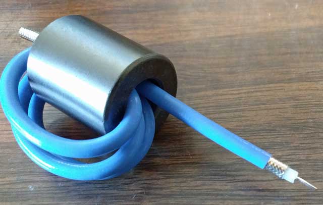
The RG402 coax supplied should be trimmed to a length of 15.5 inches
(395mm). Begin making the balun by passing the coax
through the core from left to right, leaving about 1 inch coming out of the
core on the left side. After winding the coax so it
passes through the center of the core 4 times, you'll have about 2.25 inches
(57mm) coming out of the right side.
For the single-band 6m kit, the balun does not use the ferrite core and the coax is cut to a
length of 36.5cm.
 Practice these next steps on
the short piece of RG402 left over from trimming; proceed with trimming the
balun ends and output capacitor only when you feel you've mastered the
technique.
Practice these next steps on
the short piece of RG402 left over from trimming; proceed with trimming the
balun ends and output capacitor only when you feel you've mastered the
technique.
For the balun,
remove 1/2 inch (12mm) insulation from each end,
exposing the outer conductor. Roll the coax under a knife blade to 'score' it,
at 5mm away from the insulation, taking care not to cut completely through the
shield (outer).
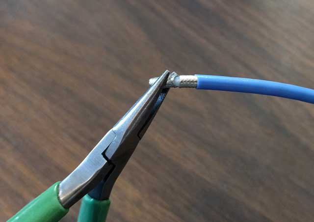 Using a pliers, bend the shield end back
and forth, breaking it away at the scored location. Once it is broken, it can
be removed with a pair of diagonal cutters, or just
pulled away from the end of the cable. This needs to be done at both ends of
the balun.
Using a pliers, bend the shield end back
and forth, breaking it away at the scored location. Once it is broken, it can
be removed with a pair of diagonal cutters, or just
pulled away from the end of the cable. This needs to be done at both ends of
the balun.
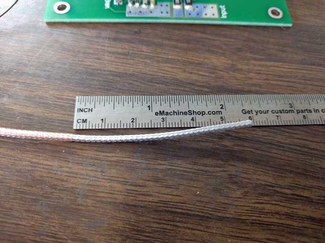
 On both ends, remove all but 2 or 3mm of insulation from around
the center conductor, taking care not to cut into the center conductor itself.
The balun is now ready to be installed.
On both ends, remove all but 2 or 3mm of insulation from around
the center conductor, taking care not to cut into the center conductor itself.
The balun is now ready to be installed.
 Beginning with the longer
lead, form the center conductor so it will lie flat on the trace in plane with
the outer, and solder it in place across the gap as shown; center conductor
soldered to the left side, outer soldered to the right.
Beginning with the longer
lead, form the center conductor so it will lie flat on the trace in plane with
the outer, and solder it in place across the gap as shown; center conductor
soldered to the left side, outer soldered to the right.
 In this step, you'll need to
bend the coax down and then level again as it exits the core, and secure the
ends as shown. Solder the outer conductor first, then bend the center conductor
down onto its trace and solder it in place.
In this step, you'll need to
bend the coax down and then level again as it exits the core, and secure the
ends as shown. Solder the outer conductor first, then bend the center conductor
down onto its trace and solder it in place.
Just one last thing
before the output board is finished; trim the remaining piece of TC18 coax (6
inches is left over) to 128mm in length, it will be used to fabricate a 30pf
coaxial capacitor. This capacitor improves output and efficiency on the higher bands
(6m in particular). Fabricate it from the coax like this:
remove 2mm of the outer Teflon insulation from one end; fold back
the shield braid from this 2mm end, and using a pair of diagonal cutters trim
it away to expose the teflon-covered center conductor
measure 117mm away from the end you just worked on and remove the
outer teflon insulation from the other end, exposing
the shield. Trim away all but 5mm of this shield and tin
it with solder
remove all but 2mm of outer insulation from the center conductor.
 The center conductor is soldered to the output trace and the
shield to ground; the other end is open and can be secured with a loop (as
shown here) so it does not contact other components or
short to ground.
The center conductor is soldered to the output trace and the
shield to ground; the other end is open and can be secured with a loop (as
shown here) so it does not contact other components or
short to ground.
The capacitor is
made from Teflon coax to enable it to withstand very high voltages; when the rf
deck is used with a reflective LPF, harmonic energy returned to this location
on some bands created voltages high enough to destroy
even 3kv capacitors.
Lastly, install the
220uf capacitor, positive lead to the VDD trace, negative to the ground foil.
 The output board is
finished.
The output board is
finished.
 Continuing now with assembling
the input board; install all components (except T1) as shown in their locations
below. C5 is to the left of R14 and under the R13 marking.
Continuing now with assembling
the input board; install all components (except T1) as shown in their locations
below. C5 is to the left of R14 and under the R13 marking.
 Cut 12 inches of RG316 and remove 5mm of insulation from the
center, exposing the shield in that location. Tin the
shield there.
Cut 12 inches of RG316 and remove 5mm of insulation from the
center, exposing the shield in that location. Tin the
shield there.
 Remove 4.25 inches insulation from each end, exposing the shield.
This is an old photo showing only 2.25 inches removed, but you get the idea....
Remove 4.25 inches insulation from each end, exposing the shield.
This is an old photo showing only 2.25 inches removed, but you get the idea....
 Holding the shield in place with your left hand, push the right
end of the shield to the left, forming a mushroom bulge about 5mm away from the
insulation on the left. Tin the 5mm of shield at the spot referenced by the red
arrow.
Holding the shield in place with your left hand, push the right
end of the shield to the left, forming a mushroom bulge about 5mm away from the
insulation on the left. Tin the 5mm of shield at the spot referenced by the red
arrow.
 Using a pair of diagonal cutters with the cutting blades parallel
to the coax, trim away the mushroom bulge and slide the loose shield off of and away from the insulated center conductor.
Using a pair of diagonal cutters with the cutting blades parallel
to the coax, trim away the mushroom bulge and slide the loose shield off of and away from the insulated center conductor.
 Install the coax into the smaller ferrite core in criss-cross fashion as shown.
![]() Position the transformer as
shown, routing the center conductor of the coax on the left across the core to
the right, then through the core from right to left.
Solder the exposed shield to the left gate trace, taking care not to bridge the
gap between the traces.
Position the transformer as
shown, routing the center conductor of the coax on the left across the core to
the right, then through the core from right to left.
Solder the exposed shield to the left gate trace, taking care not to bridge the
gap between the traces.
Do the same with
the coax on the right; routing the center conductor of the coax across the core
to the left, then through the core from left to right. Solder the exposed
shield to the right gate trace, taking care not to bridge the gap between the traces.
![]() Repeat the crossings to add
one additional pass through the core on each side.
Repeat the crossings to add
one additional pass through the core on each side.
Pass the coax on the left across the core to the right, then through
the core from right to left.
Pass the coax on the right across the core to the left, then through
the core to the right.
![]() Taking care not to cut into
the center conductor, trim insulation away from the ends and tin them.
Taking care not to cut into
the center conductor, trim insulation away from the ends and tin them.
Solder the coax
center tap to the trace below it (one end of R10 is also connected to this
trace).
Solder the center
conductor on the left to the trace at R14 and the input trace.
Solder the center
conductor on the right to the ground foil to the right of C7
![]() The input board is finished.
The input board is finished.
Installing the
Boards to the Spreader and Heat Sink
Note...the
following photos and description of the testing procedure are generic and apply
to all of the later HF variants (including the
ART1K9).
 Your heat sink should be drilled/tapped for 40-40 machine screws
(or your metric equivalent) using the pattern in this template.
Your heat sink should be drilled/tapped for 40-40 machine screws
(or your metric equivalent) using the pattern in this template.
Position your
copper spreader (with LDMOS attached) over the drilled pattern in your heat
sink.
The recommended way
to attach your LDMOS to the copper spreader is to flow-solder it as you see it
pictured here. Machined spreaders with LDMOS attached using this process are available on the parts page here.

Slide the boards
into place under the transistor tabs

Secure the board
and spreader to the heat sink with 4-40 x 5/8 machine screws (or your metric
equivalent) using flat washers under the screw heads. Once the boards are in
proper position, tighten the screws.
Solder the 4 transistor
tabs to the PC boards.
Recommended testing procedure
There
is no tuning required with this amplifier, and only one adjustment to make
(setting idling current).
- Attach input
and output coax jumpers. Your driver should be limited
to 3w on 160 through 10m, and 5w on 6m; the output should be on a dummy
load for the initial testing.
- Attach
ground, bias (12v?) and VDD (50v) wires to the RF deck, but do not apply
power yet.
- CAUTION
- for the initial test, you should place a 3 to 5 ohm
50w power resistor in series with the VDD, or
use a current-limited power supply (limited to 5a). A fuse is not fast
enough to protect against problems...if there is a short from a stray
wire strand, or a weak capacitor lets go, it will create an arc powerful
enough to vaporize board traces, transistor tabs, etc., long before a
fuse can open up.
3.
Turn on the 50v main supply voltage, but not the bias; there
should be no current drawn
4.
Turn on the bias and note the idling current drawn from the 50v
supply. Adjust IDQ for 2 amps. Note: the current drawn by the bias
supply (usually12v) is not what you are measuring here...you must measure the
idling current (IDQ) the LDMOS draws from the 50v supply.
5.
Shut off the power supply, and remove
current limiting.
- Turn the
power supply back on; drive the amp with about 1/2w, and
verify there is output power.
- If all OK in
the previous step, the amplifier can now be driven to full output. For the
BLF188xr, current should not be driven higher than 35 amps on any band;
for the MRF1K50, no higher than 40 amps. Check the performance graph in
the main technical article for typical performance.