Note: The TC-12 supplied in your kit may be white or tan in color. See this tip for cutting the tan coax type.


 The
last component to install on this board is the input inductor. For the BLF188,
this will be an 8-turn inductor installed where shown. For the ART1K6, remove
one turn to make a 7-turn inductor.
The
last component to install on this board is the input inductor. For the BLF188,
this will be an 8-turn inductor installed where shown. For the ART1K6, remove
one turn to make a 7-turn inductor.
 Install
the output balun
Install
the output balun
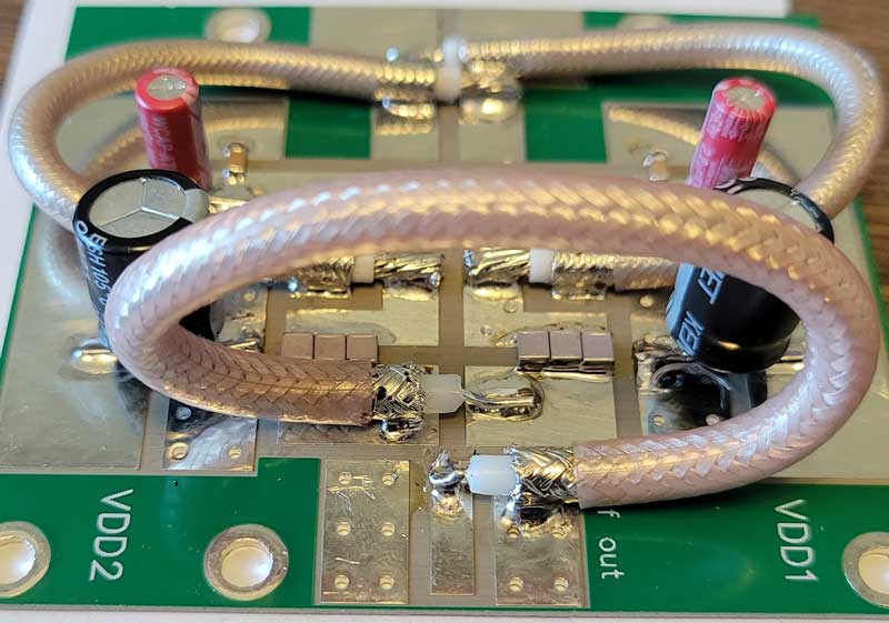
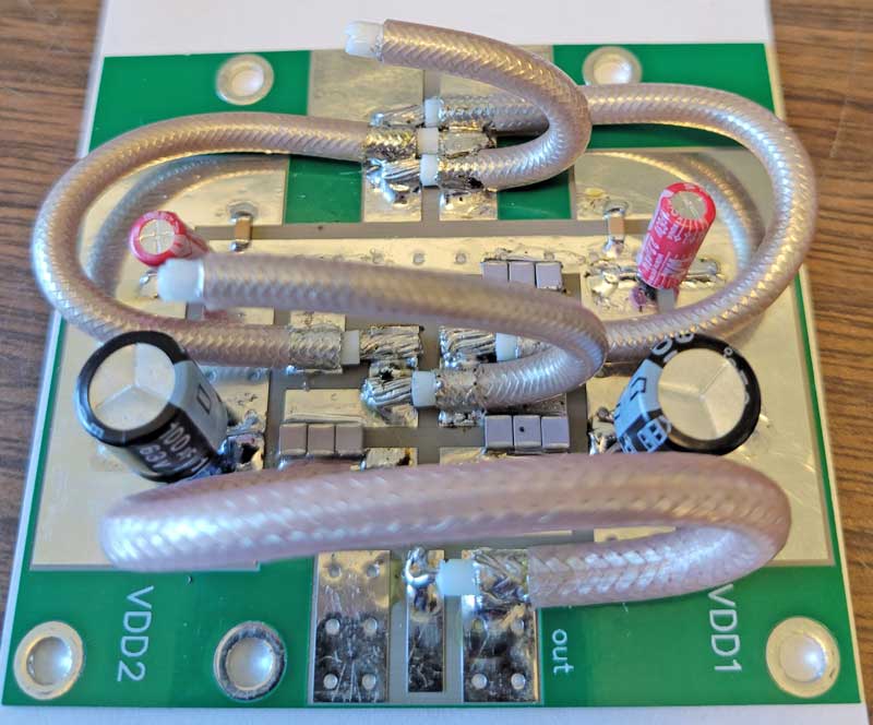 Install
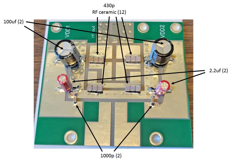
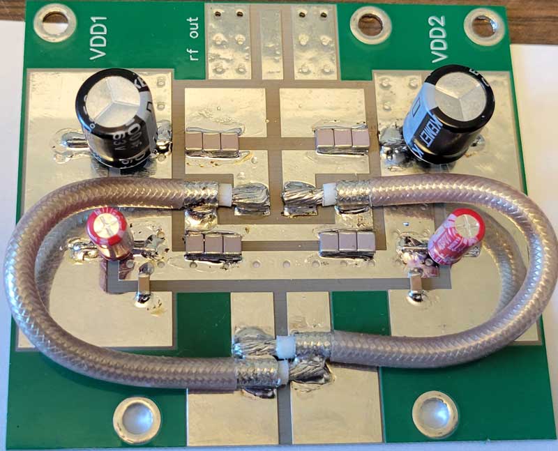
the two coaxial capacitors (the smaller one is installed near the transistor).
After soldering, bend the coax ends so the open ends are clear of other parts.
Install
the two coaxial capacitors (the smaller one is installed near the transistor).
After soldering, bend the coax ends so the open ends are clear of other parts.
 Form
the VDD drain chokes using the two pieces of #14 magnet wire supplied. Wind them
in opposite directions (easier to install) on a 1/4" dowel or other form. Bend
the ends as pictured.
Form
the VDD drain chokes using the two pieces of #14 magnet wire supplied. Wind them
in opposite directions (easier to install) on a 1/4" dowel or other form. Bend
the ends as pictured.
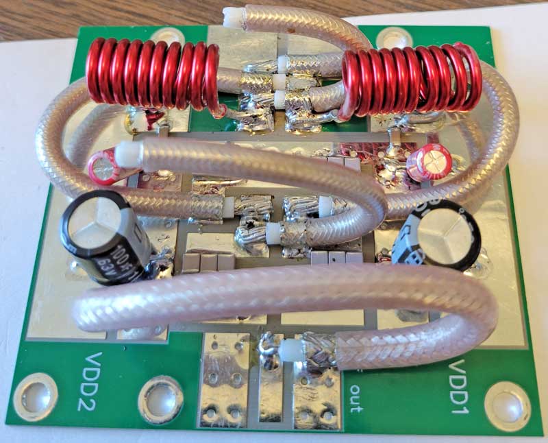 Finally,
install them as pictured here.
Finally,
install them as pictured here.
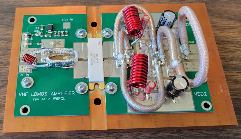 Install
the boards onto the spreader with six 4-40 by 3/16 screws and flat washers, then
solder the transistor tabs to the boards. Use a bit of flux when doing this to
ensure a smooth, even connection.
Install
the boards onto the spreader with six 4-40 by 3/16 screws and flat washers, then
solder the transistor tabs to the boards. Use a bit of flux when doing this to
ensure a smooth, even connection.
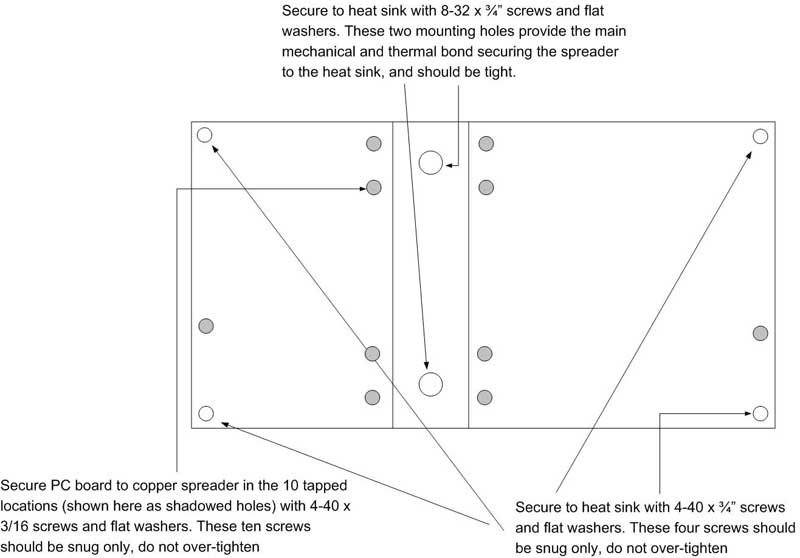
Once the boards are installed, attach the spreader to your heat sink using the other 6 mounting holes. These holes are pass-through, so your heat sink will need to be drilled and tapped to receive the screws.
The two in the center are for 8-32 by 3/4 inch (or your metric equivalent) and do not require flat washers. The four in the corners are for 4-40 by 3/4 inch (or your metric equivalent) and should also have a flat washer under the head of the screw.
 Once you are ready to
test, here's the recommended method:
Once you are ready to
test, here's the recommended method:
Connect the output to a wattmeter and a kw dummy load
Connect the input to your driver through a wattmeter
- CAUTION - for the initial test, you should place a 3 to 5 ohm 100w power resistor in series with the VDD, or use a current-limited power supply (limited to 5a). If there is a short from a stray wire strand, or a weak capacitor lets go, it will create an arc powerful enough to vaporize board traces, transistor tabs, etc.
Turn on the 50v main supply voltage, but not the bias; there should be no current drawn
Turn on the 12v bias supply and note the idling current drawn from the 50v supply. Adjust IDQ for 2 amps. Note: the current drawn by the bias supply (usually12v) is not what you are measuring here...you must measure the idling current (IDQ) the LDMOS draws from the 50v supply.
Shut off the power supply, and remove current limiting.
Drive with 1 watt or less. You should see an increase in drain current and at least 200w with 1w drive.
Increase drive until you have 1kw out. Input power should be less about 5w, and drain current about 30A at 50v