
There are some low-power commercial LNA/radio combos out there (Icom comes to mind, though they have discontinued the sale of their LNAs), but if you run higher power, or don't have one of those nifty little 10w units that is powered through the coax, you need another option.
If you've ever used a mast-mounted LNA, you may have lost it (sent it more power than it was designed for, or perhaps a UFO zapped it). I've lost one or two myself; it seems to be a rite of passage for the serious weak-signal guy. There are ways to lessen the chances of burning them out, though, and that's what this is all about...protecting that fragile LNA from our transmitters.
There are several popular methods for doing this, but I'll just be describing the two I've used and have some experience with; both methods can handle a kilowatt or more; here are the basic parameters for both:
|
Method 1 |
Method 2 |
I used the method shown on the right on 70 cm and 23 cm for years, and never lost the LNAs. It was more complex, but it certainly was bullet-proof.
Power to an LNA was supplied through a spare wire on the rotor cable, and a second lightweight transmission line (LMR-400) ran to the receiver. The transmitter line was 7/8 Heliax.
Power is applied to the LNA and relays to enable them, and disconnected by the Radio's PTT on transmit. If the power fails, the relays drop into the bypass position, which was the default state of the system.
Note that there is no way you can ever transmit into the LNA (perfect for a clumsy fellow like me).
For those who don't wish to modify their radio for split XMIT
and RCV, or cannot run any more transmission lines up the mast, an alternative
is the next method shown below.

Caution: this method works well, but there is risk associated with it's use: Losing the ALC connection to the radio will guarantee the destruction of the LNA.
A friend of mine wanted to mast-mount LNAs for 3 bands; he liked my original method, but preferred not to modify his radio for split T and R; also, his tower couldn't handle 3 more transmission lines. It was a real puzzle to solve.
This method uses the ALC input on the radio to kill the RF output while the LNA is getting out of the way.
The time required for the transfer switch to change over is typically 20 milliseconds, so the controller was designed to hold off the transmitter for at least 50 ms.
You can destroy the LNA only if your ALC line is disconnected,
otherwise you're pretty safe. Losing PTT will only keep the ALC blocked; losing
power will bypass the LNA.
 The
schematic for the controller board is shown to the right, and has been tested on
all bands/all modes on the following radios (Yaesu FT-817 / 857 / 897, Icom
IC-910H, Icom IC-7000); basically, it should work with any radio that has a
working ALC input.
The
schematic for the controller board is shown to the right, and has been tested on
all bands/all modes on the following radios (Yaesu FT-817 / 857 / 897, Icom
IC-910H, Icom IC-7000); basically, it should work with any radio that has a
working ALC input.
One circuit generates the negative bias required for blocking the transmitter through the ALC input. This bias is present whenever an LNA is switched in, and provides 40 to 50 db of RF suppression; more than enough to protect the output of the LNA.
When PTT is pressed, the LNA power is killed by Q2, and the
transfer switch goes to the bypass position. 100 ms later the ALC is released,
the transmitter recovers, and full power is reached in about a quarter of a
second; more than enough time to get the LNA safely tucked away. ALC recovery
time varies with the radio model; there is a delay of 100ms built into the
controller, and the ALC response of the radio provides additional time on top of
that. The blocking signal can be adjusted from zero to -7v.

To test the controller, I used the humble setup on the right; radio output is connected to a high-power attenuator/crystal detector into channel 1 of the scope; the time base is triggered by the PTT from the radio. ALC from the controller board is connected to the radio.
The next set of three photos (below) shows the test results on
an IC-7000.

The marker at the first major horizontal division from the left is the trigger point. The output of the IC-7000 was set to 10w on 144 MHz, and the mode set to FM. I held the max power to 10w to protect my 25w attenuator...and results were the same in all modes.
During the first 120ms following PTT closure, the transmitter
output is suppressed almost 50db. At 180ms, it has risen one vertical division
to -30dbc (about 10mw).

At 240ms, the output is at -16dbc (250mw).

And here we are at full power (10w) after 360ms.
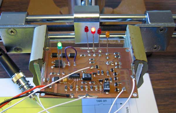
Here's a closer look at the controller board, held in a test fixture during testing.
This will soon be mounted into a suitable enclosure where the LED indicators will be moved to the front panel, along with the LNA power switches, connectors, etc.