 Begin
winding the inductor by passing one end of the wire up through the bottom of the
core opening as shown, and fold it around the body of the core.
Begin
winding the inductor by passing one end of the wire up through the bottom of the
core opening as shown, and fold it around the body of the core.Average assembly time is 3 hours. Winding all 18 inductors for the filter will take about one hour of this.
Each inductor has a specific length of pre-cut and tinned #16 magnet wire supplied for the toroid core the inductor was designed for. Check the Bill of Materials (BOM) supplied with your kit for wire length, number of turns, and core type for each inductor to be wound.
Begin
winding the inductor by passing one end of the wire up through the bottom of the
core opening as shown, and fold it around the body of the core.

Pass the long end of the wire through the top of the core opening to the right of the previous turn, and pull it through the bottom. Then pull it firmly up against the side of the core, and start the next turn. Do this for as many turns as called for in the bill of materials for that particular inductor.
Note: The number of turns is counted by how many times the wire passes through the center of the core (the inductor in this photo has 8 turns). Finish by forming the lead ends as shown.
Repeat this process for each inductor.

When you finish, your inductor set should look like this.
Caution: the high voltage/high current MC22 capacitors you will install shortly are identified and packaged in separate bags because they are not marked by the manufacturer. If you mix them up, you'll need a capacitance meter to identify them by value.
Begin installing components onto the PC board in the order recommended below, it will make assembly much easier.
First, install the 5 diodes (D1-5) with the banded end pointed down (see photo below).
Then, beginning from left to right, install the capacitor pairs one pair at a time. first 56pf, then 120pf, then 180pf, then 390pf, then 820pf, and finally on the far right, install the remaining four 910pf parts, doubled up as shown.

Next, install the 10 relays

Finally, install all of the inductor sets beginning with the left, pushing the core as close to the board as possible. It'll get a bit crowded over on the right, but it's OK, one set does not interact with the others.

The board needs to be elevated above conductive surfaces by at least 1/4", so when mounting, use spacers at the 4 mounting points in the corners. The +12v and band select wires can also be installed at this time. Wires are most easily inserted through the top, and soldered from the underside of the board.
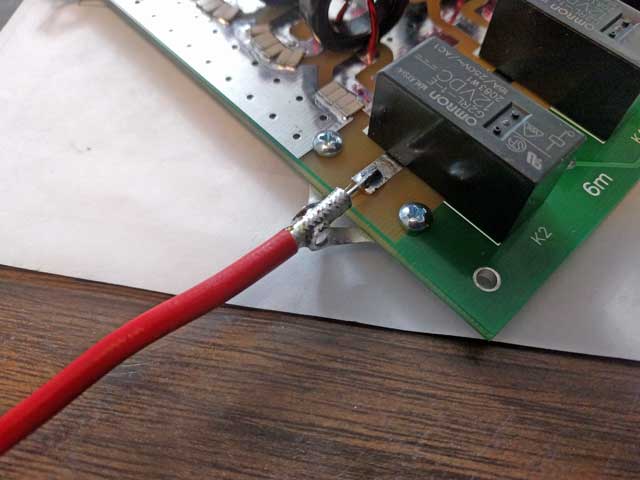
 The
easiest transition for making connections into and out of the board is to use
the two provided coax fasteners. When properly installed, each connection should
look like this photo. The recommended coax to use is RG142, it is widely
available, flexible, and will handle in excess of 2 kw through 6 meters. Here's
how to use the fasteners to make your connections:
The
easiest transition for making connections into and out of the board is to use
the two provided coax fasteners. When properly installed, each connection should
look like this photo. The recommended coax to use is RG142, it is widely
available, flexible, and will handle in excess of 2 kw through 6 meters. Here's
how to use the fasteners to make your connections:
Note: These connector instructions are for filters shipped prior to
12/2016; if your filter was supplied with #6 solder lugs instead of the flat tin
plates shown here, use these instructions instead
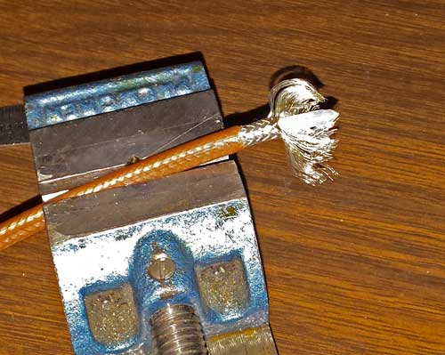 Trim
20mm of the outer insulation from the end of the coax. Using a pointed tool
(sharp tweezers will do), separate the last 10mm of shield and spread to the
sides.
Trim
20mm of the outer insulation from the end of the coax. Using a pointed tool
(sharp tweezers will do), separate the last 10mm of shield and spread to the
sides.
 Form
the shield to the underside of the coax and trim away all but about 6mm of
shield. Tin the end of this shield with solder to keep all the strands together.
Form
the shield to the underside of the coax and trim away all but about 6mm of
shield. Tin the end of this shield with solder to keep all the strands together.
 bend
the shield back under the untrimmed section. This will form a mounting foot, and
will space the coax at the proper height for connecting to the board.
bend
the shield back under the untrimmed section. This will form a mounting foot, and
will space the coax at the proper height for connecting to the board.
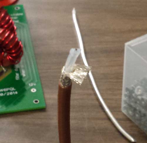
 Remove
5mm of insulation from the center conductor. While holding the tin fastener in a
vice, solder the shield foot to the fastener in the position shown.
Remove
5mm of insulation from the center conductor. While holding the tin fastener in a
vice, solder the shield foot to the fastener in the position shown.
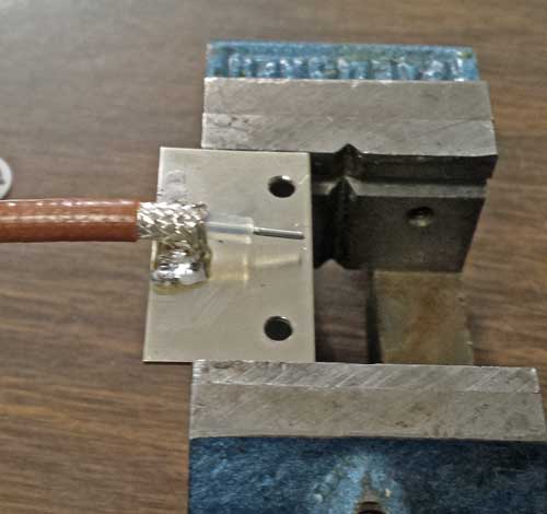
Place
the top of the fastener against the underside of the board and align to the
mounting holes. Fasten into place using 4-40 screws and locking nuts. Solder the
center conductor to the board trace, and repeat the process for the connection
on the other side.
The board is now complete and ready for tuning (follow the
procedure described in the
technical article).
The following instructions are for coax connections using #6 solder lugs (shipped after 11/2016)
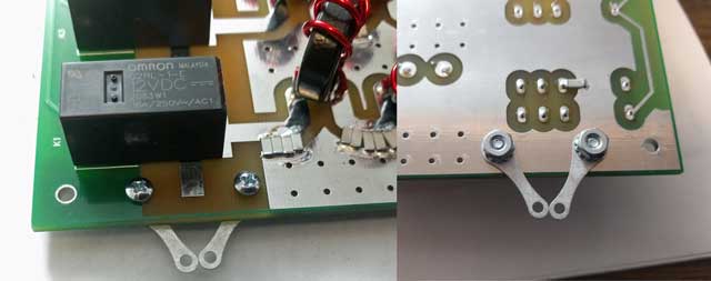 Secure
two solder lugs as shown here using the 4-40 machine screws provided; leftmost
photo is top side, rightmost photo shows the two locking nuts on the other side
securing the lugs.
Secure
two solder lugs as shown here using the 4-40 machine screws provided; leftmost
photo is top side, rightmost photo shows the two locking nuts on the other side
securing the lugs.
 Using
a pair of needle-nose pliers, bend the ends of the lugs vertical as shown. With
the lugs formed in this way, there will be considerable strength in both the
vertical and horizontal planes.
Using
a pair of needle-nose pliers, bend the ends of the lugs vertical as shown. With
the lugs formed in this way, there will be considerable strength in both the
vertical and horizontal planes.
Shown here is RG402 coax, though you can use any coax (such as RG142) capable of handling the power.
Prepare your coax by removing 20mm insulation covering the outer conductor.
Next, remove 10mm insulation covering the center conductor.
With the center conductor laying on top of the board and soldered to the board trace, taking care not to move the coax, position the lugs against the sides of the outer conductor and solder them to the outer.
Repeat this procedure for the other RF connection.