 Mount
it as shown in the left photo, with most of the capacitor body over the bottom
trace. Solder into place.
Mount
it as shown in the left photo, with most of the capacitor body over the bottom
trace. Solder into place.First, locate the 35pf trimmer capacitor supplied in your kit. The photo to the right shows the back side of this capacitor, and the reason for this first note: the trimmer must be mounted so it is not centered between the two gate traces, it must be offset so the round part in the center does not sit above the opposite trace. If centered, it will short the two traces together.
Mount
it as shown in the left photo, with most of the capacitor body over the bottom
trace. Solder into place.
Pre-set the slotted adjustment as shown, with the slot vertical. This will
put the capacitor at mid-range, and very close to resonance with the rest of the
input circuit.

Note: do not install the boards to the heat spreader yet, this will be done in the last step
Install all of the components on both boards except for the coax baluns.
The 10pf chip capacitor must be installed just to the right of the green trimmer capacitor.
The 5pf (green) mica capacitor is aligned across the drain traces with it's
right edge even with the place where the traces narrow.

The 58mm coaxial capacitor should be installed 30mm from the drain edge of
the PC board. The open end should be formed with a
gentle bend up and away from other components.

The 5nh inductor is installed across the gate pads as
shown here.

As shown in this photo, each drain bypass should consist of one each .001uf, .01uf, .1uf and 1uf chip capacitor as well as the
100uf electrolytic. The order isn’t important, so long as all capacitors are
lined up where shown, with the electrolytic around the corner.

This next set of photos shows how to configure the bias feed resistors for
various bias supply voltages. Most builders will probably want to use the 12v
configuration, which is the bias output from the "ultimate" control board
offered on the parts page, but the bias feed can be anything from 12 to 50v.


Install the coax baluns as shown on the right.
Slide the boards under the transistor tabs (transistor should have been previously flow-soldered to a copper spreader).
Here is a video showing how to flow-solder your LDMOS to the spreader.
Here is the drilling template for the spreader.
Secure (but do not over-tighten) the boards to the spreader with 4-40 screws (2.5mm if you are using metric hardware with your own spreader).
Using a bit of liquid flux, solder the LDMOS tabs to the board.
 The
addition of the following components is recommended to ensure
unconditional stability by
applying
degenerative feedback. This feedback is most effective at very low
frequencies where these LDMOS devices have excessive gain. Without the
degenerative feedback, and under certain rare conditions,
self-oscillation can occur and destroy the LDMOS.
The
addition of the following components is recommended to ensure
unconditional stability by
applying
degenerative feedback. This feedback is most effective at very low
frequencies where these LDMOS devices have excessive gain. Without the
degenerative feedback, and under certain rare conditions,
self-oscillation can occur and destroy the LDMOS.
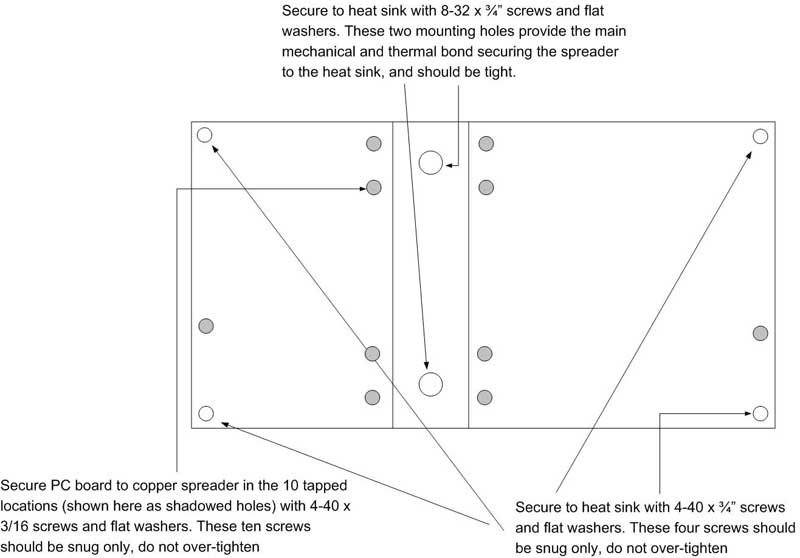 Fasten
the spreader to a suitable heat sink using the guide on the right. Use a
very thin coating of heat sink compound between spreader and heat sink (too
much, and it will actually impair heat transfer).
Fasten
the spreader to a suitable heat sink using the guide on the right. Use a
very thin coating of heat sink compound between spreader and heat sink (too
much, and it will actually impair heat transfer).
Turn on the 50v main supply voltage, but not the bias; there should be no current drawn
Turn on the bias and note the idling current drawn from the 50v supply. Adjust IDQ for 1 amp. Note: the current drawn by the bias supply (usually12v) is not what you are measuring here...you must measure the idling current (IDQ) the LDMOS draws from the 50v supply.
Shut off the power supply, and remove current limiting.
