

Begin Assembly by trimming the coaxial pieces:
Note: The TC-12 supplied in your kit may be white or tan in color. See this tip for cutting the tan coax type.


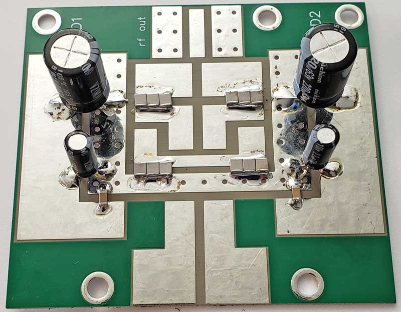
The first components to mount are the capacitors.
The 430pf RF capacitors are clustered in groups of 3 at the four locations
shown. Then mount the two 1206 size 1000pf capacitors, the two 2.2uf and two 220uf
electrolytics (observe the polarity on the electrolytics).
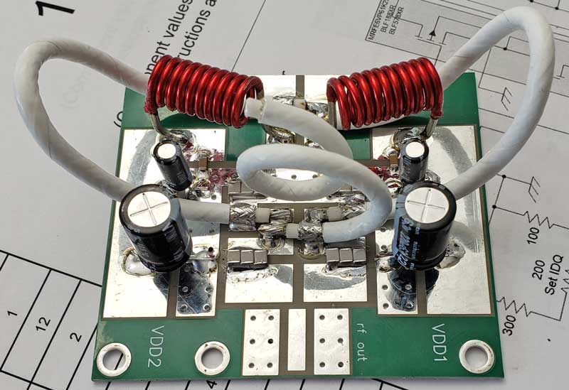
 TC-12 coax transformers are next. The position of the connection point at the
drain traces will affect the match; the loop at the left should be lined up with the
transition line where the trace transitions from wide to narrow, on the side of
the transition toward the top of the photo. The
loop on the right should be placed right up against it on the other side of the
transition as shown.
TC-12 coax transformers are next. The position of the connection point at the
drain traces will affect the match; the loop at the left should be lined up with the
transition line where the trace transitions from wide to narrow, on the side of
the transition toward the top of the photo. The
loop on the right should be placed right up against it on the other side of the
transition as shown.
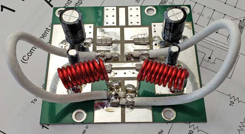
Wind the VDD chokes using the two pieces of #14 magnet wire supplied (the ends are already tinned). Wind them on a 1/4" form (such as a wooden dowel, tool shaft or a small pipe) with close-spaced windings as you see them here.
Remove them from the 1/4" form and install the two 10-turn VDD drain inductors
 The
larger
coaxial capacitor is next, formed in a way that keeps the open end away from
other components.
The
larger
coaxial capacitor is next, formed in a way that keeps the open end away from
other components.
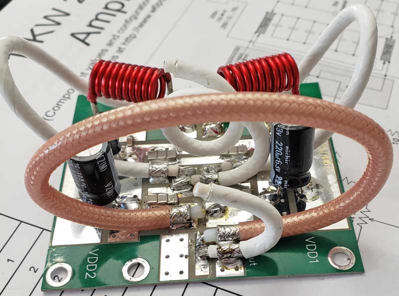 The
RG142 balun is next, followed by the smaller coaxial capacitor. Position this part
so the open end is away from other components.
The
RG142 balun is next, followed by the smaller coaxial capacitor. Position this part
so the open end is away from other components.
The output board is finished.
 Except for the input transformer, mount all input board components. The bias
has been set up for 12v feed. See the
assembly instructions for the 500w 70cm amplifier for other bias feed
configurations.
Except for the input transformer, mount all input board components. The bias
has been set up for 12v feed. See the
assembly instructions for the 500w 70cm amplifier for other bias feed
configurations.
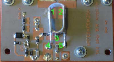 Mount
the input transformer. It must be soldered to the board at the 5 points shown
(this is an old prototype photo, but you get the idea).
Mount
the input transformer. It must be soldered to the board at the 5 points shown
(this is an old prototype photo, but you get the idea).
The input match will be affected by the distance between the transformer and
the transistor. Where you see it placed here is normally the optimum position.
However, if your input match is off frequency, moving the transformer a little
closer to the transistor will raise the frequency, and moving it closer to point
3 will lower it.
Slide the boards under the transistor tabs (transistor should have been
previously flow-soldered to a copper spreader).
Here is a video showing how to flow-solder your LDMOS to the spreader.
Here is the drilling template for the spreader.
Secure the boards to the spreader with 4-40 x 3/16 screws and flat washers.
Do not over-tighten. Use some liquid flux, and solder the boards to the tabs as shown.

Turn on the 50v main supply voltage, but not the bias; there should be no current drawn
Turn on the bias and note the idling current drawn from the 50v supply. Adjust IDQ for 2 amps. Note: the current drawn by the bias supply (usually12v) is not what you are measuring here...you must measure the idling current (IDQ) the LDMOS draws from the 50v supply.
Shut off the power supply, and remove current limiting.